


Product outline
F372A is a digital indicator integrated with a strain gauge sensor that can display physical quantities such as pressure, load and torque in waveforms.
- 2000 times/sec. high-speed processing
- Work no. can set up up to 16 types
- Can start measurement even there is no external signal
- Analog monitor output
- Variety of interfaces
- 3.5 inch color LCD module & touch panel
- Multi calibration function
- Alarm function
- Can confirm forcs pattern before measurement start. (Pre Trigger)
Voltage output is proportionate to the input signal making the recording on recorder convenient.
Approx. 2 V per 1 mV/V strain gauge input
RS-232C/ CC-Link/ DeviceNet/ D/A output/ BCD output (Sink type/ Source type)
Setting operation made easy via direct touch on the touch panel.
Stores calibration values for 4 ch portions and can be selected via touch panel or external signal
Monitors if the measured value is abnormal
– Hi/Lo limit for in comparison setting
– A/D input range
– Overflow
– Digital zero regulation value
Waveform display
Input signal from the sensor is displayed as real-time waveformdisplay.
Greatly shortens the adjustment time during the machine’s start-up.
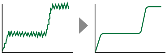
Assuredly cancels vibration, noise and unwanted inputs.
The filtering results can be confirmed from the waveform.
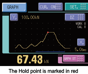
Greatly improves the machine’s reliability through its in-process operational check.
The machine’s operation can be consistently monitored through the waveform and hold points in-process check.
Can also be used when investigating causes of the machine’s trouble.
Work selection (multi hold)
This function compares the required points in the waveform with the Hi/Lo limits. F372A stores up to 16 types of settings (settings such as types of holds or Hi/Lo limits) which can be selected via external signals.
■ Hold types
Sample, Peak, Bottom, P-P, Average, Inflection Point, Relative Maximum, Relative Minimum, Relative Difference
■ Setting of range
– Externally specified range (Peak, Bottom, P-P, Average)
– Externally + Time specified range (Peak, Bottom, P-P, Average)
– Level + Time specified range (Peak, Bottom, P-P, Average)
– Level (Peak, Bottom)
Storing of measured data and setting values
<Double Hold>
Specifically combined two types of hold functions are performed simultaneously in one detection. Hold modes can be selected from 26 modes shown below.
HI/LO limit comparisons of the difference value between the presently measured hold value and the previously measured hold value can be made.
Difference value = Present hold value (indicated value) – Previous hold value
<Relative Value Comparison>
HI/LO limit comparisons of the difference (relative value) between hold value A and hold value B can be made.
Specifications
Analog section|Display section|Setting section|Hold function|Comparison function|Calibration value selection|External signal|Interface|General specifications|Attachments
| Analog section | |
| Excitation voltage | DC 10 V, 2.5 V±5% (depending on settings) Output current: within 120 mA |
|---|---|
| Signal input range | -3.0 to +3.0 mV/V |
| Accuracy | Non-linearity: within 0.02% FS ±1 digit (at 3.0 mV/V input) Zero drift: within 0.5 μV/℃ RTI Gain drift: within 0.01%/℃ |
| Analog filter | Low pass filter (-6 dB/oct.) Selectable at 30 Hz, 100 Hz, 300 Hz, 1 kHz |
| A/D converter | Speed: 2000 times/sec., Resolution: 24 bit (binary) Approx. 1/30000 at 3.0 mV/V input |
| Analog monitor output | Output level: Approx. 2 V per 1 mV/V input;Load resistance: 2 kΩ or more |
| Display section | |
| Display unit | TFT color LCD |
|---|---|
| Display area | 71(W) mm × 53(H) mm |
| Dot structure | 320 × 240 dot |
| Measured value | 5 digits: -99999 to +99999, Sign: Minus sign on most significant digit |
| Setting section | |
| Comparison functions | HH, Hi, Lo, LL, Hysteresis, alarm Hi, alarm Lo, near zero, comparison timing, comparison output selection |
|---|---|
| Hold setting | Hold mode, detection start level, detection time, level detection condition, sample point shift value, detection end level, average sample number, inflection minimum slope, inflection front slope time, inflection removal value, detection start condition, relative minimum count, relative magnification |
| Graph setting | Graph mode, Y-axis (load) start point, Y-axis (load) end point, X-axis (time) end point, plotting start level, interval time, plotting start level conditions |
| Calibration setting | Excitation voltage, zero calibration, equivalent input calibration, actual load calibration, calibration value selection, unit, minimum scale, digital offset, digital zero limit |
| Operation setting | Digital filter, analog filter, backlight lighting time, language change, SI/F print, motion detect, zero tracking, monitor output filter, display color of measured value, B5 function selection, B6 OFF detection standby time, B8 OFF detection standby time, measured work input change, control input change, password |
| RS-232C setting | Communication mode, baud rate, character length, stop bit, parity bit, delimiter, flow control |
| Extended comparison function | Previous value comparison, relative value comparison |
| Extended hold function | Double hold, auto reset change, hold value update, sample trigger change, hold cancel at DZ, hold END timing |
| Extended graph function | Pre-trigger display |
| Extended operation function | Digital filter characteristics, average time at DZ, RUN output format |
| Extended option | BCD output data format |
| Hold function | |
| Hold | 1) Sample, 2) Peak, 3) Bottom, 4) P-P, 5) Average, 6) Inflection Point, 7) Relative Maximum, 8) Relative Minimum, 9) Relative Difference, 10) Sample&Peak, 11) Sample&Bottom, 12) Sample&P-P, 13) Sample&Average, 14) Sample&Inflection Point, 15) Sample&Relative Maximum, 16) Sample&Relative Minimum, 17) Sample&Relative Difference, 18) Peak&Bottom, 19) Peak&P-P, 20) Bottom&P-P, 21) Average&Peak, 22) Average&Bottom, 23) Average&P-P, 24) Relative Maximum&Relative Minimum, 25) Relative Maximum&Relative Difference, 26) Relative Minimum&Relative Difference |
|---|---|
| Comparison function | |
| Can set 4 different settings from Hi limit, Lo limit, etc |
|
| Calibration value selection | |
| Stores up to 4 types of calibration value that can be interchanged | |
| External signal | |
| External output signal (8 points) | HI/LO comparison output (HH, HI, OK, LO, LL)/ RUN output/ Hold end output/ Graph plotting end output Vce = 30 V (max), Ic = 30 mA (max) |
|---|---|
| External input signal (10 points) | Work selection input/ Hold control input/ Digital zero input (DZ)/ Graph plotting control input/ Calibration selection input Ic = 10 mA or less |
| Interface (Only one option can be installed) |
|
| SIF | 2-wire type serial interface |
|---|---|
| 232 | RS-232C communication interface |
| CCL | CC-Link interface (Option) |
| ODN | DeviceNet interface (Option) |
| BCO | BCD parallel data output interface (Sink type)(Option) |
| BSC | BCD parallel data output interface (Source type)(Option) |
| DAV | D/A converter voltage output (Option) |
| DAI | D/A converter current output (Option) |
| General specifications | |
| Power supply voltage | DC 24 V (±15%) |
|---|---|
| Power consumption | 5 W typ. |
| Operating conditions | Operation temperature -10℃ to +40℃ Storage temperature -20℃ to +60℃ Humidity: 85% RH or less (non-condensing) |
| Inrush current (typ) | 55 A, 1 msec (cold start at room temperature) |
| Dimensions | 96(W) × 96(H) × 138(D) mm (Not including projections) |
| Weight | Approx. 1.0 kg |
| CE marking certification | EMC Directives EN61326-1 |
| Attachments | |
| FCN series I/O connector (with cover) | 1 |
|---|---|
| Operation manual | 1 |
| BCD output connector (when BCD output option is selected) | 1 |
| Mini screwdriver (when D/A converter option is selected) | 1 |
| CC-Link connector (when CC-Link option is selected) | 1 |
| DeviceNet connector (when DeviceNet option is selected) | 1 |
| Analog I/O connector terminal block (Already mounted on the main unit) |
1 |
Optional accessories
| Model | |
| CA372-I/O | Cable with FCN connector at one-end 3 m |
|---|---|
| CA600-BCDCNV | FCN connector 32p-57・36p cabtire cable 0.3 m |
| CA81-232X | miniDIN-D-Sub9p cross cable 1.5m |
| CN50 | FCN series I/O connector (with cover) (Same as the attachment) |
| CN55 | FCN series I/O connector (with diagonal cover) |
| CN60 | Round DIN 8p connector for RS-232C |
| CN51 | BCD output connector |
| CN71 | CC-Link connector |
| CN72 | Double row connector for CC-Link |
| CN80 | Analog I/O connector terminal block (Same as the attachment) |
| CND01 | DeviceNet connector |
| DTC2 | Case for F372A (with AC power supply) |
| GMP96×96 | Rubber packing |
| TSU01 | DC Lightning surge unit |
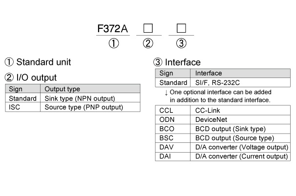
Structure of product code
Please note that there are possibilities of individual differences in a color tone on display devices such as LEDs, fluorescent display tubes and LCDs due to manufacturing process or production lots.
Download
|
Product catalogue(PDF)
|
⇒Download Page | |
|---|---|---|
|
Operation manual(PDF)
|
||
|
External dimension
|
DXF
(ZIP) |
|
|
PDF
|
||
|
Support tools
|
||
|
Software
|
||
