


Product outline
A full-scale weighing indicator developed exclusively for measuring system.
- Setting values can be stored in each of the 100 kinds of codes so that code selection and measuring can be conveniently performed.
- Excellent operability
Function-prioritized key input and Vacuum Fluorescent Display (VFD) tube for improved visibility. - Direct PLC connection
CC-Link and DeviceNet interface. - High resolution
1/10000 resolution at all input range is assured.
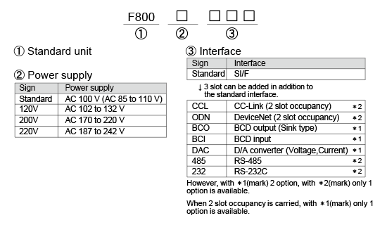
Structure of product code
Specifications
Analog section|Setting section|Display section|External signal|General specifications|Attachments
| Analog section | |
| Excitation voltage | DC 10 V±5%, Output current; within 120 mA Remote sense type(Up to 4 350 Ω load cells can be connected in parallel) |
|---|---|
| Zero adjustment range | 0 to approx. 2 mV/V Rough adjustment: Digitally controlled by rough adjustment circuit. Fine adjustment: Automatic adjustment by digital processing. |
| Span adjustment range | 0.3 to 2.0 mV/V Rough adjustment: Digitally controlled by rough adjustment circuit. Fine adjustment: Automatic adjustment by digital processing. |
| Min. input sensitivity | 0.3 μV/count |
| Accuracy | Non-linearity: within 0.01% FS (Typ. 0.005% FS at room temperature) Zero drift: within 0.1 μV/°C RTI (Typ. 0.08 μV/°C) Gain drift: within 15 ppm/°C (Typ. 5 ppm/°C) Noise: within 0.1 μVp-p RTI (0.1 to 10 Hz) |
| Analog filter | Bessel type low-pass filter (-12 dB/oct.), Selectable from 2, 4, 6, 8 Hz |
| A/D converter | Speed: 100 times/sec.(10 mS) Resolution: 16 bit (binary) |
| Setting section | |
| Setting method | ・ Keyboard operation (keyboard with a key click buzzer) ・ External setting is available by installing RS-232C option |
|---|---|
| Setting value storage | ・ Initial set values: NOV RAM (Non-volatile RAM) ・ Other set values: C-MOS RAM with backup of a lithium battery (Effective for more than 5 years depending on usage conditions and storage environment) |
| Setting value protection | Setting operation can be locked to prevent unauthorized modifications of default values and calibration by malfunction (LOCK) |
| Setting item | ・ Calibration: Zero calibration/ Span calibration/Balance weight value/ Capacity/ Min. scale division/ Over Net/ Over Gross/ Display frequency/ Decimal point/ 1/4 Scale display ON/OFF/ Unit/ Gravitational acceleration compensation ・ Comparative setting1: SP1/ SP2/ CPS/ Final/ Under/ Over/ AFF reg/ Compensation input timer ・ Comparative setting2: Near zero/ Lo/ Hi/ Preset tare weight/ Comparison inhibit time/ Judging time/ Compare time/ Discharging time/ AZ time/ Judging times/ Sequence mode ・ Function setting: Digital filter/ Motion Detection/ Weighing function1/ Weighing function2/ Weighing function3/ Function key inhibited/ RS-232C/ ID number setting/ Analog filter/ Zero tracking/ Measurement law/ Extended selection1 |
| Display section | |
| Display unit | Eight (8) digits, 12 mm Original Vacuum Fluorescent Display |
|---|---|
| Display | 5 digits Sign: Minus sign on most significant digit |
| Unit | Selectable from g, kg, t, N, none |
| Display frequency | Selectable from 3, 6, 13, 25 times/sec. (internal 100 times/sec.) |
| Status display | SET / LOCK / HOLD / Z.ALM / STAB. / TARE / NET / GROSS / RUN / HI / LO / NEAR Z. / SP1 / SP2 / SP3 / OVER / GO / UNDER / COMPL / D.CHG / AFC | Set value display | CODE / FINAL /OVER / UNDER / SP1 / SP2 / CPS |
| External signal | |
| Output signal (16) |
Near zero / SP1 / SP2 / SP3 / under / go / over / complete / discharge / Lo / Hi / stable / weight error / error / final error / RUN Transistor open collector output (Emitter = COM terminal) Output is set to LO when transistor is ON. Vceo = 30 V (max), Ic = 120 mA (max) |
|---|---|
| Input signal (24) |
Gross or net / digital zero / tare on / tare reset / hold or judge / feed or discharge / accumulation command / accumulation clear / code setting / start / stop / discharge command / compulsory discharge command / discharge gate open / discharge gate close / code assign selection Set to ON when shorted to COM terminal through contact point (relay, switch etc.) or non-contact point (transistor, open collector output such as TTL etc.) Ic = 10 mA or lower |
| Interface Please inquire from our sales office for the combination of options that can be installed. |
|
| SIF | 2-wire type serial interface (standard) |
|---|---|
| CCL | CC-Link interface (Option) |
| ODN | DeviceNet interface (Option) |
| BCO | BCD parallel data output interface (Option) |
| BCI | BCD parallel data input interface (Option) |
| DAC | D/A converter (Option) |
| 485 | RS-485 communication interface (Option) |
| 232 | RS-232C communication interface (Optional) |
| General specifications | |
| Power supply voltage | AC 85 to 110 V, 102 to 132 V, 170 to 220 V, 187 to 242 V (Please specify when ordering) 50/60 Hz |
|---|---|
| Power consumption | 14 VA typ. |
| Operating conditions | Operation temperature: -10°C to +40°C Storage temperature: -40 to +80°C Humidity: 85% RH or less (non-condensing) |
| External dimension | 130(W)×207(H)×150(D) mm (Not including projections) |
| Weight | Approx. 3 kg |
| Attachments | |
| AC input cord (Nominal rating 125 V) 2 m | 1 |
|---|---|
| Spare fuse (1 A) | 1 |
| Mini driver | 1 |
| Load cell input connector (JR connector) | 1 |
| 57 series 50p connector | 1 |
| Operation manual | 1 |
| CC-Link connector (when CC-Link option is selected) | 1 |
| DeviceNet connector (when DeviceNet output option is selected) | 1 |
| BCD output connector (when BCD output option is selected) | 1 |
| BCD input connector (when BCD input option is selected) | 1 |
| Optional accessories | |
| CAAC2P-P2 | AC input cord 2 m (Same as the attachment) |
|---|---|
| CAAC3P-P2 | AC input cord 2 m |
| CAAC3P-CEE7/7-P1.5 | AC input cord (voltage resistance: 250 V) 1.5 m |
| CN3P-2P | 3P-2P converter plug for AC input cord |
| CA4131 | (6-wired) cable with JR connector at one end 3 m |
| CA4230 | JR-PRC (6-wired) conversion relay cable 0.3 m |
| CA4311 | JR-PRC (6-wired) conversion relay cable 1 m (4-wired to 6-wired) (for 520A) |
| CN10 | Load cell connector (JR connector) (Same as the attachment) |
| CN21 | BCD input/ output connector |
| CN22 | 57 series 50p connector for external input/output (Same as the attachment) |
| CN35 | D-sub25p connector for RS-232C |
| CN71 | CC-Link connector |
| CN72 | Double row connector for CC-Link |
| CND01 | DeviceNet connector |
Option
| Model | Interface (Optional slot・・・3: Please refer to the following table for the combination that can be installed.) |
| CCL | CC-Link interface |
|---|---|
| ODN | DeviceNet interface |
| BCO | BCD parallel data output interface |
| BCI | BCD parallel data input interface |
| DAC | D/A converter |
| 485 | RS-485 communication interface |
| 232 | RS-232C communication interface |
(Ref.) Assortment of options
| Number of install OP | BCD OUT (BCO) |
BCD IN (BCI) |
D/A (DAC) |
RS-232C (232) |
RS-485 (485) |
DeviceNet (ODN) |
CC-Link (CCL) |
||
|---|---|---|---|---|---|---|---|---|---|
| 1 | ◎ | ||||||||
| ◎ | |||||||||
| ◎ | |||||||||
| ◎ | |||||||||
| ◎ | |||||||||
| ◎ | |||||||||
| ◎ | |||||||||
| 2 | ◎ | ◎ | |||||||
| ◎ | ◎ | ||||||||
| ◎ | ◎ | ||||||||
| ◎ | ◎ | ||||||||
| ◎ | ◎ | ||||||||
| ◎ | ◎ | ||||||||
| ◎ | ◎ | ||||||||
| ◎ | ◎ | ||||||||
| ◎ | ◎ | ||||||||
| ◎ | ◎ | ||||||||
| ◎ | ◎ | ||||||||
| ◎ | ◎ | ||||||||
| ◎ | ◎ | ||||||||
| ◎ | ◎ | ||||||||
| ◎ | ◎ | ||||||||
| 3 | ◎ | ◎ | ◎ | ||||||
| ◎ | ◎ | ◎ | |||||||
| ◎ | ◎ | ◎ | |||||||
| ◎ | ◎ | ◎ | |||||||
| ◎ | ◎ | ◎ | |||||||
| ◎ | ◎ | ◎ | |||||||
| Number of install OP | BCD OUT (BCO) |
BCD IN (BCI) |
D/A (DAC) |
RS-232C (232) |
RS-485 (485) |
DeviceNet (ODN) |
CC-Link (CCL) |
||
Please note that there are possibilities of individual differences in a color tone on display devices such as LEDs, fluorescent display tubes and LCDs due to manufacturing process or production lots.
Download
|
Product catalogue(PDF)
|
⇒Download Page | |
|---|---|---|
|
Operation manual(PDF)
|
||
|
External dimension
|
DXF
(ZIP) |
|
|
PDF
|
||
|
Support tools
|
||
|
Software
|
||
