


| Product outline | Specifications | Download |
Product outline
F805AT adopts a color LCD touch panel which enables simple and comfortable operation by greatly enhancing the visibility of weight display, various setting values display and status display. It provides high-speed A/D conversion and digital processing capability at an operating speed of 1000 times/sec There are substantial interfaces that allow direct connection to major PLCs including MITSUBISHI CC-Link and OMRON DeviceNet. F805AT, which was developed specifically for weighing systems, is a full-fledged device of an all-in-one type that deserves to be called the top-of-the-line Weighing indicator.
- The weighing indicator suitable for use in any kind of applications, either in measuring equipments requiring high level of sequence such as hopper scales and packing scales or in general platform scales having simple application.
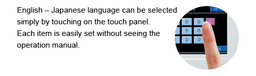
- 5.7 inch color LCD module & LCD touch panel
- Direct PLC connection
A wide range of interfaces (optional) is available for the networking of measuring work through its CC-Link and DeviceNet connections. - High speed A/D conversion and powerful digital processing capabilities of 1000 times/sec., for rapid response to input signal.
- High resolution
1/10000 (at valid 1/4 scale division) at all input range is assured.
(1/40000 at invalid 1/4 scale division) - Selectable powerful filter
Bessel low pass filter for the removal of mechanical vibration, and moving averaging digital filter are pre-installed. - Free power source
Caters for AC 100 to 240 V without having to switch over.
DC power supply can also be specified when making your order.
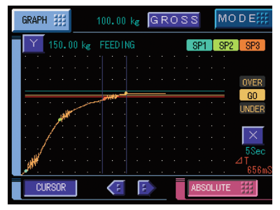
Waveform display function
The analog input signal from the loadcell is displayed in real-time waveform.
The cut-off speed for bulk or fine feeding can be adjusted on the spot by setting it based on the displayed real-time waveform.
Convenient substantial functions for measuring
Measuring sequence function
Sequential control can be performed without connecting external PLC etc.
It enables to perform the delicate measuring with the combination of various setting and timer such as adjust feeding for insufficient measuring, discharge gate control at feed- measuring and inserting digital filter automatically at stable condition etc.
Equivalent input calibration function
Calibration of scale generally conducted with actual load.
When it is difficult to apply actual load to the scale due to structural condition, the calibration can be done by inputting weight value corresponds to output value of load cell through the touch panel.
Auto free fall compensation function
The variation of actual free fall which becomes big factor of measuring error can be corrected automatically.
Zero tracking function
Slow zero drift or shift of zero point due to temperature change etc. is automatically corrected.
Compensation feeding function
Fine feeding has been repeated for certain intervals until the fine feeding reaches to the final.
Memory for 100 types of codes
Up to 100 types of setting value such as Final value, CPS (a fall),
Adjust Feeding etc. can be saved. Selective measuring can be conducted through touch panel or external signal.
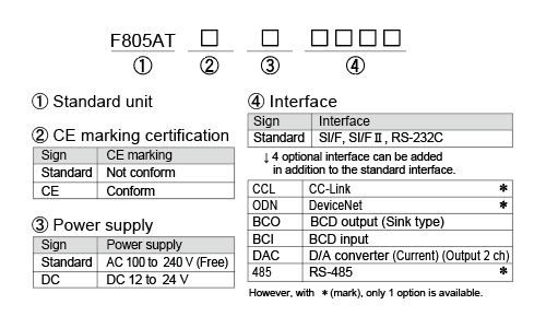
Structure of product code
Specifications
Analog section|Setting section|Display section|External signal|Interface|General specifications|Attachments|Optional accessories
| Analog section | |
| Excitation voltage | DC 10 V or 5 V±5% (depending on settings), Output current; within 120 mA, remote sense type (Up to 4 350 Ω load cells can be connected in parallel.) |
|---|---|
| Zero adjustment range | 0 to approx. 2 mV/V Rough adjustment:Digitally controlled by rough adjustment circuit. Fine adjustment: Automatic adjustment by digital processing. |
| Span adjustment range | 0.3 to 2.0 mV/V Rough adjustment:Digitally controlled by rough adjustment circuit. Fine adjustment: Automatic adjustment by digital processing. |
| Min. input sensitivity | 0.3 μV/count (at valid 1/4 scale division) 0.075 μV/count expanded (at invalid 1/4 scale division) |
| Accuracy | Non-linearity: within 0.01%/FS (Typ: 0.005%/FS at room temperature) Zero drift: within 0.1 μV/°C RTI (Typ: 0.08 μV/°C) Gain drift: within 15 ppm/°C (Typ: 5 ppm/°C) Noise: within 0.1 μVp-p RTI (0.1 to 10 Hz) |
| Analog filter | Bessel low-pass filter (-12 dB/oct.) Selectable from 2, 4, 6, 8 Hz |
| A/D converter | Speed: 1000 times/sec (Convertible to 200 times/sec.) Resolution: 16 bit (binary) |
| Setting section | |
| Setting method | – Setting by touch panel operation – Setting from host computer via RS-232C is also possible |
|---|---|
| Setting value storage | – Default: NOV RAM (nonvolatile RAM) – Other setting values: C-MOS RAM with backup of a lithium battery |
| Setting value protection | Setting operation can be locked to prevent unauthorized modifications of default values and calibration by malfunction (LOCK) |
| Display section | |
| Display unit | TFT color LCD (Display area 115 (W) x 86 (H) [mm], 320 x 240 dot |
|---|---|
| display | 5 digits, Signs: Minus sign on most significant digit |
| Unit Selectable | t, kg, g, N, lb, none |
| Display frequency | Selectable from 3, 6, 13, and 25 times/sec. (System speed is 200 times/sec. or 1000 times/sec. (depending on settings)) |
| Status display | LOCK, HOLD, ZALM, STAB, TARE, RUN, HI, LO, NZ, SP1, SP2, SP3, OVER, GO, UNDER, COMPL, DCHG |
| Setting value display | Code, Final, Over, Under, SP1, SP2, Compensation |
| External signal | |
| External Output signal (16) |
-Near Zero, SP1, SP2, SP3, Under, Go, Over, Complete, Discharge, Lo, Hi, Stable, Weight Error, Error, Final Error, Run or total final -Transistor open collector output (Emitter = COM terminal) Output is set to LO when transistor is ON. Vceo = 30 V (max), Ic = 120 mA (max) |
|---|---|
| External Input signal (24) |
-Gross And Net Switching, Digital Zero, Tare On, Tare Off, Hold or Judgement, Feed And Discharge Switching, Accumlation Command, Accumulation Clear, Start, Stop, Discharging Command, Code Assign, Compulsory Discharge Command, Discharge Gate Open, Discharge Gate Close, Code Assign Selection, Graph Drawing -Set to ON when shorted to COM terminal through contact point (relay, switch etc.) or non-contact point (transistor, open collector etc.) Ic = 10 mA or lower |
| Interface Interface option: Up to 4 options allowable. Serial communication interface (*) is 1 option only. |
|
| SIF | 2-wire type serial interface (standard) |
|---|---|
| SI2 | 2-wire high speed bidirection serial interface (standard) |
| 232 | RS-232C communication interface (standard) |
| CCL | CC-Link interface (Option)* |
| ODN | DeviceNet interface (Option)* |
| BCO | BCD parallel data output interface (Option) |
| BCI | BCD parallel data input interface (Option) |
| DAC | D/A converter interface (Option) |
| 485 | RS-485 communication interface (Option)* |
| General specifications | |
| Power supply voltage | AC 100 to 240 V (+10% -15%) (Free power source at 50/60 Hz) DC 12 to 24 V (±15%) (For DC, please specify when ordering) |
|---|---|
| Power consumption | 8 W typ. |
| Inrush current (Type) | 15 A, 5 msec: 100 V AC average load condition (cold start at room temperature) 30 A, 5 msec: 200 V AC average load condition (cold start at room temperature) 10 A, 0.5 msec: 12 V DC average load condition (cold start at room temperature) 35 A, 0.4 msec: 24 V DC average load condition (cold start at room temperature) |
| Operating conditions | Operating temperature: -10 to +40°C; Storage temperature: -20 to +60°C Humidity: 85% RH (non-condensing) |
| External dimension | 174(W) × 135(H) × 159(D) mm (Not including projections) |
| Weight | Approx. 2.3 kg |
| CE marking certification | EMC directives EN61326-1 Safety standard EN61010-1, EN62311 (Please specify requirement for CE marking certified product when making your order) (DC power supply is not certificationed to CE Marking.) |
| Attachments | |
| AC Supply cord *1 (Nominal rating 125 V) 2 m |
1 |
|---|---|
| AC input cord converter plug *1 *2 |
1 |
| Mini driver | 1 |
| Load cell connector (JR connector) | 1 |
| 57 series 50p connector | 1 |
| Ferrite core *2 | 2 |
| Operation Manual | 1 |
| CC-link connector (when CC-Link option is selected) | 1 |
| DeviceNet connector (when DeviceNet option is selected) | 1 |
| BCD output connector (when BCD output option is selected) | 1 |
| BCD input connector (when BCD input option is selected) | 1 |
| D/A converter connector (when D/A converter option is selected) | 1 |
*1 To be attached only for AC power supply specification.
*2 Attached only in products with CE marking.
| Optional accessories | |
| CAAC2P-P2 | AC input cord 2 m(F805A)(Same as the attachment) |
|---|---|
| CAAC3P-P2 | AC input cord 2 m(F805ACE) |
| CAAC3P-CEE7/7-P1.5 | AC input cord (voltage resistance:250 V) 1.5 m |
| CA4131 | (6-wired) cable with JR connector at one end 3 m |
| CA4230 | JR-PRC (6-wired) conversion relay cable 0.3 m |
| CA4311 | JR-PRC (6-wired) conversion relay cable 1 m (4-wired to 6-wired) (for 520 A use) |
| CN3P-2P | 3P-2P converter plug for AC input cord(Same as the attachment) |
| CN10 | Load cell connector (JR connector)(Same as the attachment) |
| CN20 | D/A converter connector |
| CN21 | BCD input/output connector |
| CN22 | 57 series 50p connector for external I/O(Same as the attachment) |
| CN34 | D-Sub9p connector for RS-232C |
| CN71 | CC-Link connector |
| CN72 | Double row connector for CC-Link |
| CND01 | DeviceNet connector |
| GMP165×130 | Rubber packing |
| TSU02 | Lightning surge unit |
| TSU03 | DC lightning surge unit |
Option
|
Model
|
Interface
|
Slots installed
|
| BCO | BCD parallel data output interface (General-purpose slot option…3 slots installed (① to ③below)) |
1 to 3 |
|---|---|---|
| BCI | BCD parallel data input interface (General-purpose slot option…3 slots installed (① to ③below) |
1 to 3 |
| DAC | D/A converter interface (General-purpose slot option…3 slots installed (① to ③below)) |
1 to 3 |
| 485 | RS-485 communication interface (Advanced communication slot option…1 slot installed (④ below)) |
4 |
| ODN | DeviceNet interface (Advanced communication slot option…1 slot installed (④ below)) |
4 |
| CCL | CC-Link interface (Advanced communication slot option…1 slot installed (④ below)) |
4 |
Please note that there are possibilities of individual differences in a color tone on display devices such as LEDs, fluorescent display tubes and LCDs due to manufacturing process or production lots.
Download
|
Product catalogue(PDF)
|
⇒Download Page | |
|---|---|---|
|
Operation manual(PDF)
|
||
|
External dimension
|
DXF
(ZIP) |
|
|
PDF
|
||
|
Support tools
|
||
|
Software
|
||
