Product outline
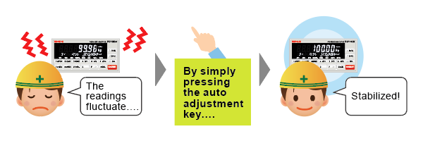
High performance filter & Auto filter adjustment
With combination of low pass filter (0.1 to 300 Hz) which corresponds to various vibration and moving average filter (OFF, 2 to 512) that is effective for periodic vibration, automatic searching for optimal value with accuracy and stability can be achieved. (You can manually adjust settings too).
SD card slot
You can write and read setting parameters from SD cards, while recording weighing results & data when abnormalities occur.
■ Calibration value & Error logs are automatically recorded
You can identify the indications of faulty load cells and replacement timing.
Date & time of errors occurred can be displayed, as well as the record of how the errors are made (through key control, communication, I/O, etc).
■ Data recording of weighing results
Monitor management of raw material, equipment operation rate and so on.
Long-term trend can be observed as well.
■ Restore setting parameters with just one touch
・You can copy setting parameters to another replaced FC1000.
・Multiple FC1000s can use the exact same settings.
・You can restore the initial setting when you first install FC1000. (It will be saved as initial value separately from the setting parameters).

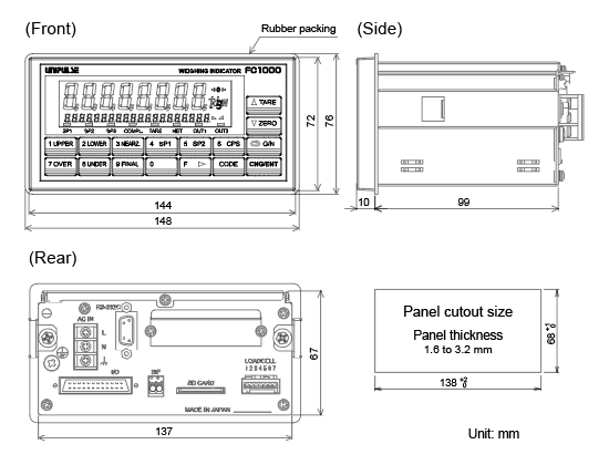
Depth of 99 mm
Miniaturization of control panel & panel space saving.
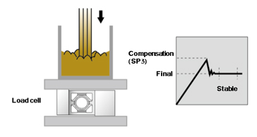
Minus compensation
High-pressure liquid filling & powder feeding can be done.
Equivalent to IP65 protection
By placing the rubber seal when mounting on the panel, the front panel can be protected from moisture and dust damage.
High sampling rate & resolution
High-Speed A/D conversion and powerful digital processing capability of 1200 times/sec. High display resolution of 1/100000 (max).
Load cell signal level display (-2.5 mV/V to 5.1 mV/V)
The output signal level of load cell can be displayed in mV/V for monitor purpose.
Malfunction indicator or faulty sensor can be differentiated easily.
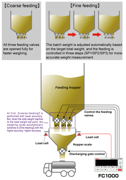
Total weight control function
The batch weighing with a low capacity scale enables the fast and accurate measurement of larger total weight.
Bright white LCD display with the useful 20 digits sub display

6 digit display
24 bit A/D convertor enables 6 digit display.
Memory for 32 weight settings
32 different weight settings can be saved in the memory and selected through I/O or interface.
Batch weighing can be performed easily.
Equivalent input calibration
Theoretical calibration can be performed easily by registering the capacity and rated output of load cells.
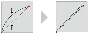
Multipoint calibration (linearization)
Three additional points can be defined in the middle between zero and span for better linearity.
Even though the scale has poor linearity, it can be corrected to be a highly accurate scale.
Structure of product code
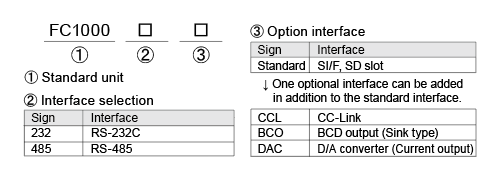
External dimension
Specifications
Analog section|Display section|Setting section|External signal|Interface|General specifications|Attachments
| Analog section | |
| Excitation voltage | DC 5 V±5% Output current:90 mA Remote sense type (Up to 6 350 Ω load cells can be connected in parallel) |
|---|---|
| Signal input range | -2.5 to +5.1 mV/V |
| Zero adjustment range | Automatic adjustment by digital processing -2.5 to +2.0 mV/V |
| Span adjustment range |
Automatic adjustment by digital processing 0.02 to +3.0 mV/V |
| Linearization function | Can calibrate up to 3 points other than zero/span |
| Min. input sensitivity | 0.15 μV/count |
| Accuracy | Non-linearity: within 0.01% FS Zero drift: 0.0002% FS/℃ Typ. Gain drift: 1 ppm/℃ Typ. |
| Filter | Digital low-pass filter 0.1 to 300 Hz Moving average filter OFF, 2 to 512 times |
| A/D converter | Speed: 300 times/sec., 1200 times/sec. (dependeing on setting) Resolution: 24 bit (binary) |
| Display section | |
| Display Unit | 7-segment LCD display Main display: 8 digit(14.4 mm character height), Sub-display: 20 digit (4.3 mm character height) |
|---|---|
| Display value | 5 digit sign: negative display at the highest digit (Up to 6 digits) |
| Unit | None / kg / g / t / lb / N |
| Decimal point | 0, 0.0, 0.00, 0.000 |
| Weight errors | “LOAD”: sensor signal level is above the signal input range, “-LOAD”: the sensor signal level is below the signal input range, “OFL1”: the Net weight is over the limit, “OFL3”: the GROSS weight is over the limit |
| Display frequency | 1, 3, 6, 13 or 25 times/sec. |
| Status display | SP1 / SP2 / SP3 / COMPLETE / TARE ON / NET / OUT1 / OUT2 |
| Setting section | |
| Setting method | By operating the membrane keys or through interface |
|---|---|
| Memory of set value | Default settings: stored in NOV.RAM (non-volatile RAM) Time: backed up by lithium battery Other setting values: stored in F-RAM (non-volatile RAM) |
| Protection of set value | Settings can be protected with the software LOCK |
| Setting item | – Upper limit / Lower limit / Near zero / Set point 1 / Set point 2 / Compensation / Over / Under / Final – Comparison inhibit time 1 / Judging time / Complete output time / Compensation Feeding Time / Number of times for AZ / Number of times for judging / Auto free fall compensation regulation values / Comparison inhibit time 2 / Preset tare value – Weighing function 1 / Weighing function 2 / Weighing function 3 / Sequence mode / Key invalid-LOCK / Discharging Time / Motion detection(Period – Range) / Zero tracking (Period) / Zero tracking (Range) – Balance weight value / Minimum scale division / NET weight over / GROSS weight over /DZ limitation value / Display selection / Gravitational acceleration / Sub-display mode /Sub-display selection – D/A output mode / D/A zero scale adjustment / D/A full scale adjustment / RS-232C/RS-485 setting / RS-232C/RS-485 ID / Transmission delay time / CC-Link I/F setting / CC-Link station number setting / Setting LOCK – Input Signal selection 1 / Input Signal selection 2 / Input Signal selection 3 / Output Signal selection 1 /Output Signal selection 2 / Output Signal selection 3 / Output Signal selection 4 / Status display selection / Sampling speed – Total count / SP0 / Total comparison mode / Target total weight (high 4) /Target total weight (under 5) / Total SP1 (high 4) / Total SP1 (under 5) – SD card command 1 / SD card command 2 / Time and Date / Auto adjustment filter / Digital low pass filter / Moving average filter / Extended function selection 1 / Extended function selection 2 / Total weight control function |
| External signal | |
| Output signal (12) | Selectable/configurable Open collector output Vceo = 30 V, Ic = 120 mA |
|---|---|
| Input signal (8) | Selectable/configurable Non-voltage contact input (internal circuit power supply voltage 12 V) |
| Interface | |
| SIF | 2-wire type serial interface |
|---|---|
| SDC | SD card slot |
| 232 or 485 | Select either RS-232C or RS-485 interface |
| CCL | CC-Link interface (option) |
| BCO | BCD parallel data output interface (Option) |
| DAC | D/A converter current output (Option) |
| General specifications | |
| Power supply voltage | AC 100 to 240 V (+10% -15%) (free power source 50/60 Hz) |
|---|---|
| Power consumption | 5 W typ. |
| Operating conditions | Operating temperature: -10 to +50℃ Storage temperature: -20 to +60℃ Humidity: 85% RH or less (non-condensing) |
| Dimension | 144(W) × 72(H) × 109(D) mm (Not including projections) |
| Weight | Approx. 850 g |
| Attachments | |
| AC input cord (nominal rating 125 V) 3 m | 1 |
|---|---|
| FCN series I/O connector (with cover) | 1 |
| Load cell input connector | 1 |
| Operating tool | 1 |
| Jumper wire | 2 |
| SD card (1 GByte) | 1 |
| Rubber seal for dust & drop-proof protection | 1 |
| Quick manual | 1 |
| CC-Link connector (when CC-Link option is selected) | 1 |
| BCD output connector (when BCO option is selected) | 1 |
| D/A converter connector (when DAC option is selected) | 1 |
| Optional accessories | |
| CAAC2P-B3 | AC input cord 3 m (Same as the attachment) |
|---|---|
| CAAC3P-B3 | AC input cord 3 m |
| CA325AC3P-B3 | AC input cord 3 m |
| CAAC3P-CEE7/7-B2 | AC input cord (voltage resistance: 250 V) 2 m |
| CA325AC3P-CEE7/7-B2 | AC input cord (voltage resistance: 250 V) 2 m |
| CN21 | BCD output connector |
| CN34 | D-sub9p connector for RS-232C |
| CN50 | FCN series I/O connector (with cover) (Same as the attachment) |
| CN55 | FCN series I/O connector (with diagonal cover) |
| CN71 | CC-Link connector |
| CN72 | Double row connector for CC-Link |
| CN78 | Load cell input connector (Same as the attachment) |
| CN86 | 3p connector D/A converter |
| SD1G | SD card 1 GByte |
| SD2G | SD card 2 GByte |
| SD16G | SD card 16 GByte |
| SD32G | SD card 32 GByte |
Please note that there are possibilities of individual differences in a color tone on display devices such as LEDs, fluorescent display tubes and LCDs due to manufacturing process or production lots.
Download
|
Product catalogue(PDF)
|
⇒Download Page | |
|---|---|---|
|
Operation manual(PDF)
|
||
|
External dimension
|
DXF
(ZIP) |
|
|
PDF
|
||
|
Support tools
|
||
|
Software
|
||


