


Product outline
The best solution for OK/NOK judgment of press fitting and caulking application !!
High responsiveness of 5 kHz to fully utilize the performance of Super Cell !!
A fluctuation of force is shown as a waveform.
- Two-dimensional OK/NOK judgement can be performed with a load cell and displacement sensor.
- Analog monitor output
Voltage output is proportionate to the input signal making the recording on recorder convenient.
Approx. 2 V per 1 mV/V strain gauge input - 25000 times/sec. high-speed processing
- Variety of interfaces
USB / CC-Link / DeviceNet / EtherNet/IP / Ethernet / PROFINET IO - 4.3-inch color LCD module & touch panel
Operation can be effortlessly performed by a direct touch on the touch panel.
OK/NOK judgment with 2 ch sensor inputs !!
Two-dimensional OK/NOK judgement can be performed with a load cell and displacement sensor.
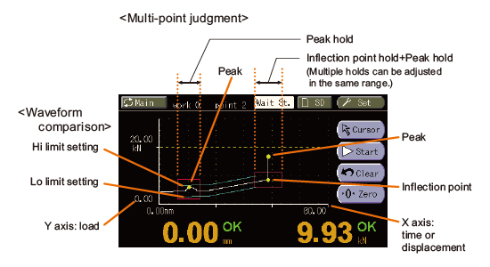
Comparison & hold function by waveform display
■ Waveform comparison
This function compares the actual measurement waveform against the setup High/Low limit waveforms and will give out an NOK judgment when any of the point exceeded the preset High/Low limit waveforms.
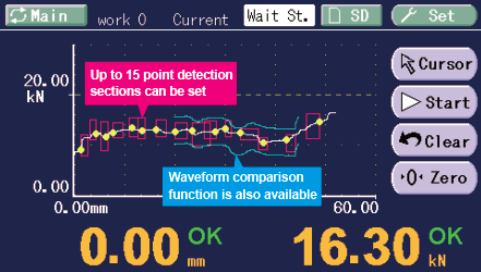
■ Multi-point judgment
OK/NOK judgment can be performed on multi points in one process. (e.g. The start point and end point of press fitting can be judged respectively.)(Max. 5 points)
Example of use

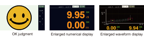
Improved usability
4.3 inch wide display provides excellent visibility.
Main display configuration can be selected to keep it as simple as possible by eliminating unnecessary information.
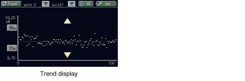
Trend display is helpful for preventive maintenance
Trend of the zero-point shift and hold values can be monitored to find any irregularities for preventing breakdown of machines.
In addition, the master settings can be registered so that operator can compare with the current settings to see if there are any differences.
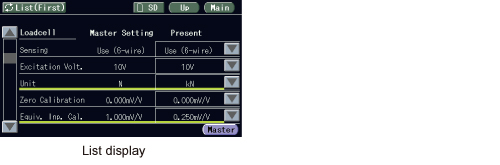
Changed setting items are highlighted!
Master and current set values are listed up for checking the changed setting items easily.
Set values can be edited directly on the list without going into each setting menu.
* Except for waveform comparison settings.
Saved measured data (waveform) on the SD card can be displayed afterwards
Measured data and set values can be saved in the SD card. Data can be converted to CSV format easily for editing with Microsoft Excel.

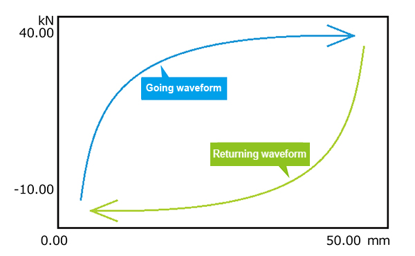
FS2000-HYS Hysteresis specifications
Standard:Can see going waveform
>>> Hysteresis specifications:Can see outgoing and return waveform
<Can choose comparison method!>
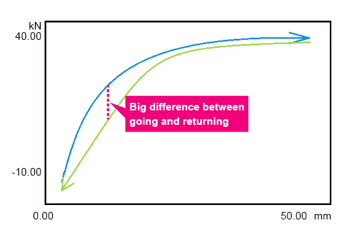
●Differential waveform comparison
Judgment of OK/NOK by the difference between going and returning.
Recommended for below usage:
– Expansion and contraction of the spring
– Rotating the steering wheel clockwise, counterclockwise, etc.
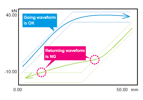
●Standard waveform comparison
OK/NOK judgment for going and returning waveform.
Recommended for below usage:
– Torque hinges used to open and close doors
– Shock absorbers that absorb the impact of tires, etc.
FS2000-MHP Multi hold point specifications
Standard:OK/NOK judgement up to 5 points
>>>Multi hold point specifications:OK/NOK judment up to 15 points
Specifications
Sensor input(Standard)|Sensor input(Multisensor input)(option:MLT or MLT2)|Analog voltage output|Display section|COMP. & JUDGE. function|Preventive maintenance support|External signal|Interface|General specifications|Attachments
| Sensor input(Standard) | |
| Sensor input for load (Fixed as strain gauge input)(6-wire) | |
| Excitation voltage | DC 2.5, 5, 10 V±10% (depending on settings) Output current: Within 30 mA |
|---|---|
| Signal input range | -2.0 mV/V to +2.0 mV/V |
| Accuracy | Non-linearity: Within 0.02%/FS ±1 digit (at 2.0 mV/V input) Zero drift: Within 0.1 μV/℃ RTI Gain drift: Within 15 ppm/℃ |
| Low-pass filter | Selectable from 10 Hz to 10 kHz(-6 dB/oct.)(at A/D converter speed 25000 times/sec) Selectable from 2 Hz to 2 kHz(-6 dB/oct.)(at A/D converter speed 5000 times/sec) |
| A/D converter | Speed: Selectable from 25000 times/sec., 5000 times/sec. Resolution: 24 bit (binary)Effective resolution: Approx. 1/20000 against 2.0 mV/V |
| Sensor input for displacement (Pulse input:Line driver) | |
| Max. input frequency | 1 MHz |
| Internal count range | Approx. 1,000,000 |
| Adaptable rotary encoder | Output: Incremental type 2-phase output (A/B phase signal output) Also capable of single-phase output (A-phase input used. All pulses are counted as in the plus direction.) Output stage circuit specification: Line driver (Based on RS-422) |
| Sensor input, Multisensor input (Option:[MLT]or[MLT2]) | |
| Sensor input for load (strain gauge)(6-wire) …Same as standard |
|
| Sensor input for displacement (Pulse input: open collector) … Other than output circuit, spec is standard [MLT] |
|
| Output stage circuit specification | Open collector |
|---|---|
| Sensor input for displacement (Pulse input: line driver) … Same as standard [MLT2] |
|
| Voltage input…[MLT1][MLT2] | |
| Signal input range | -10 to +10 V |
| Absolute maximum rating | ±15 V or more |
| Input impedance | Approx. 1 MΩ or more |
| Accuracy | Non-linearity: Within 0.02% FS±1 digit (at 10 V input) Zero drift: Within 0.2 mV/℃ RTI Gain drift: Within 0.01%/℃ |
| Low-pass filter | Selectable from 10 Hz to 10 kHz (-6 dB/oct.) (at A/D converter speed 25000 times/sec.) Selectable from 2 Hz to 2 kHz (-6 dB/oct.) (at A/D converter speed 5000 times/sec.) |
| A/D converter | Speed: Selectable from 25000 times/sec., 5000 times/sec. Resolution: 24 bit (binary) Effective resolution: Approx. 1/20000 against 10 V |
| Analog voltage output | Output level: Approx. 2 V per 1.0 mV/V input Load resistance: 2 kΩ or more |
|---|
| Hysteresis specifications |
Multi-point comparison and waveform comparison are possible by measuring going/returning with one waveform. (Can choose go/return difference comparison) Number of drawing points: 1000 points for going, 1000 points for returning |
|---|
| Multi hold point specifications |
Multi hold: 15 points Sampling speed: 5000 Hz |
|---|
| Display section | |
| Display | 4.3 inch TFT color LCD module Display area: 95.0(W) × 53.9(H) mm Dot configuration: 480 × 272 dot |
|---|---|
| Display frequency | Fixed at 3 times/sec. |
| COMP. & JUDGE. function | |
| Multi point comparison mode 16 ch (setting values can be stored) |
Capable of judging up to 5 hold points at the same time. Sample, Peak, Bottom, P-P, Relative Maximum, Relative Minimum, Inflection Point(A,B,C,D), Average, End displacement |
|---|---|
| Waveform comparison mode 16 ch (setting values can be stored) |
Compares the actually measured waveform against the preset HI/LO waveforms. The overall measured waveform will be compared against the preset HI/LO and if any of its points exceeds the preset waveform, then the measured waveform will be NOK. |
| Preventive maintenance support | |
| Trend display | Showing the trend of measurement data to help finding irregularities at early stage. |
|---|---|
| Statistics | Using the latest 10000 measured data. Displaying number of measurement, OK, NOK |
| Screen capture | Saves screen capture data as bmp data. |
| Work name edit | Work name can be edited and displayed for each Work No. |
| Setting list display | Changed setting items comparing to master set values are highlighted. |
| User management | Login ID and Password |
| External signal | |
| Output signal 16 points |
Point judgment (load, displacement)/ Load overload/ Measurement complete/ Waveform comparison judgment/ Load & displacement OK/ CPU OK/ SD card OK/ Timing output 1,2 Output Type: Sink type/ source type selectable. (Source Type is option: [ISC]) Output transistor ON at signal ON. To connect an input unit like a PLC, connect plus common for sink type, and minus common for source type. Rated voltage: 30 V Rated current: 30 mA |
|---|---|
| Input signal 16 points |
Load digital zero/ Displacement adjustment/ Measurement start/ Measurement end/ HOLD1 to 5/ Reset/ Forcibly light up the backlight/ Touch panel lock/ Work change Input type: Plus common/Minus common selectable. (Minus common is option: [ISC]) To connect a transistor, connect NPN output type (sink type) for plus common and PNP output type (source type) for minus common. |
| Interface Only one option can be installed. |
|
| USB | USB interface |
|---|---|
| CCL | CC-Link interface (option) |
| ODN | DeviceNet interface (option) |
| EIP | EtherNet/IP interface (option) |
| ETN | Ethernet interface (option) |
| PRT | PROFINET IO interface (option) |
| Option MLT or MLT2 only one option can be installed. |
|
| ISC | I/O source board |
|---|---|
| MLT | Multisensor input |
| MLT2 | Multisensor input |
| Special option | |
| FS2000-HYS | Special option which records and judge a reverse waveform (Hysteresis Specifications) |
|---|---|
| FS2000-MHP | Special opeton which enables to detect hold points up to 15 (Multi Hold Point Specifications) |
| General specifications | |
| Power supply voltage | DC 24 V (±15%) |
|---|---|
| Power consumption | 6 W typ. |
| Operation condition | Operation temperature : -10℃ to +40℃ Storage temperature : -20℃ to +60℃ Humidity: 85% RH or less (non-condensing) |
| Dimensions | 132(W) × 98(H) × 110(D) mm (Not including projections) |
| Weight | Approx. 1.0 kg |
| CE marking certification | EMC directive EN61326-1 |
| Attachments | |
| I/O connector (with cover) | 1 |
|---|---|
| Analog connector | 1 |
| Operating tool | 1 |
| SD card 1 GByte | 1 |
| Operation manual | 1 |
| CC-Link connector (when CC-Link option is selected) | 1 |
| DeviceNet connector (when DeviceNet option is selected) | 1 |
Optional accessories
| Model | |
| CN36 | I/O connector (with cover)(Same as the attachment) |
|---|---|
| CN71 | CC-Link connector |
| CN72 | Double row connector for CC-Link |
| CN77 | Analog connector(Same as the attachment) |
| CND01 | DeviceNet connector |
| SD1G | SD card 1 GByte(Same as the attachment) |
| SD2G | SD card 2 GByte |
| SD16G | SD card 16 GByte |
| SD32G | SD card 32 GByte |
| CA81-USB | USB cable (Type-A-Bmini) 1.8 m |
| TSU03 | DC lighting surge unit |
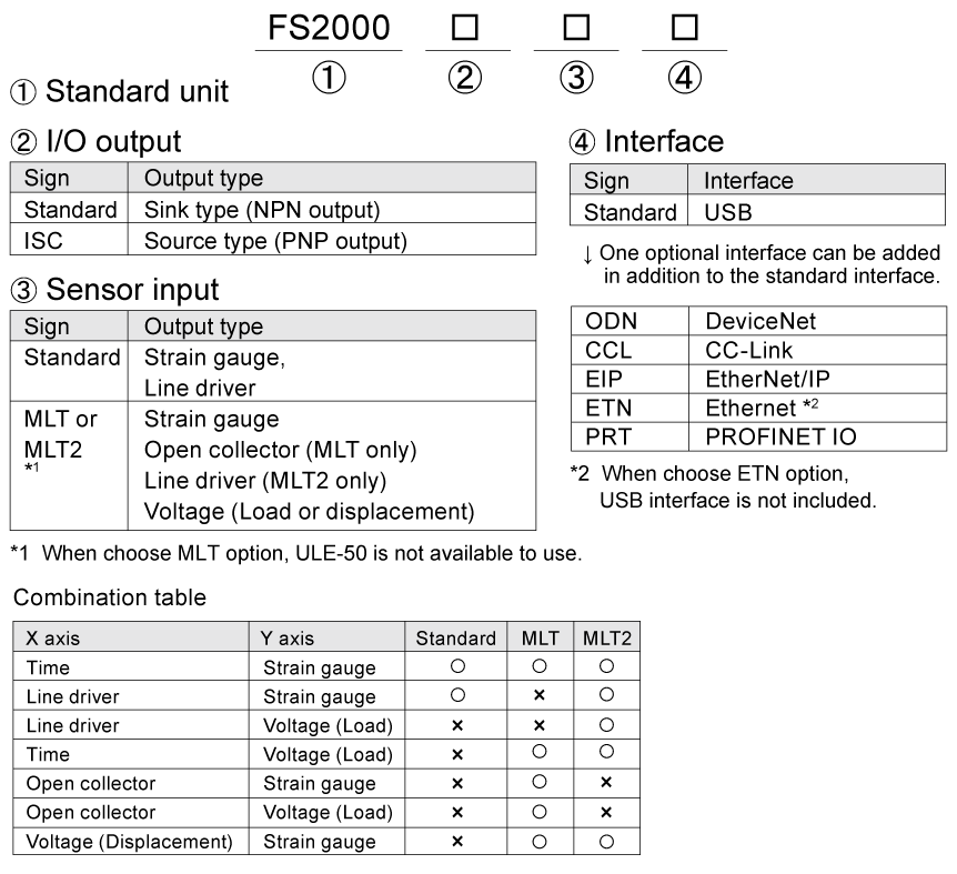
Structure of product code
Please note that there are possibilities of individual differences in a color tone on display devices such as LEDs, fluorescent display tubes and LCDs due to manufacturing process or production lots.
Download
|
Product catalogue(PDF)
|
⇒Download Page | |
|---|---|---|
|
Operation manual(PDF)
|
||
|
External dimension
|
DXF
(ZIP) |
|
|
PDF
|
||
|
Support tools
|
||
|
Software
|
||
