Product outline
By connecting UTMⅡ with the rotary encoder option, the relationship between torque and angle (or displacement/distance) change can be displayed in a graph (waveform), which in turn, is used for thorough waveform comparison.
There are two modes for waveform comparison useful for various purposes: “continuous” and “average” mode.
In “continuous mode,” HI and/or LO control outputs will be turned ON when the sensor input level goes over or below the high/low limit for predetermined number of times.
In “average mode,” a mean/average waveform data is calculated from a preset numbers of waveform data for OK/Not OK (NG) evaluation.
Features
■ Torque monitor for UTMⅡ/UTMV
■ Waveform display of torque variation against angles
■ Suitable for low-speed rotation and direct-acting applications
■ Hold function
■ Upper/lower limit of displacement against initial torque can be compared
■ Save measurement data and setting values in an SD card
■ Easy connection to UTMⅡ/UTMV with one cable
■ Operation power source can be supplied to the UTMⅡ/UTMV. (also to an optional rotary encoder)
Application example
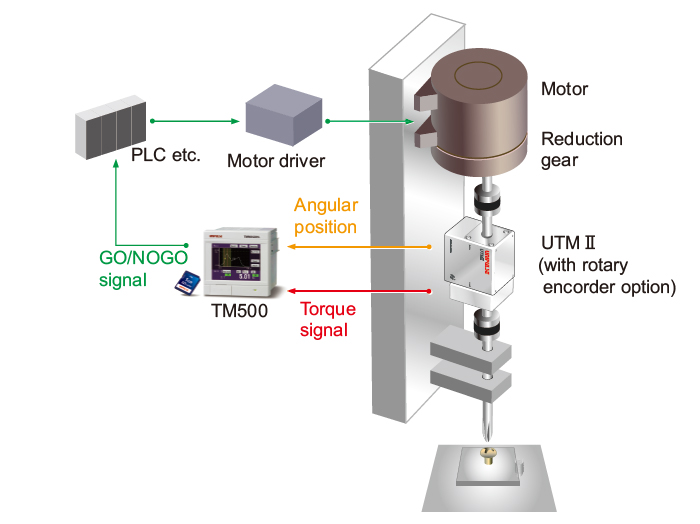
<Screw driver with torque monitoring>

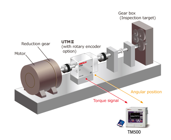
<Physical sensory test>

Specifications
Analog section|Display section|Setting section|External I/O signal|Interface|General specifications|Attachments
| Analog section | |
| Torque input | -5 to +5 V Input impedance:1 MΩ or more |
|---|---|
| Accuracy | Non-linearity : Within 0.02% FS±1 digit Zero drift : Within 0.2 mV/℃ RTI Gain drift : Within 0.01%/℃ |
| Analog filter | Low pass filter (-6 dB/oct.) Selectable from 30 Hz, 100 Hz, 300 Hz, 1 kHz |
| A/D converter | ・ Speed : 4000 times/sec ・ Resolution : 24 bit (binary) Approx. 1/30000 with respect to 5 V |
| Voltage Monitor output | Linked to the output voltage of the torque meter |
| Pulse input (Open collector) |
Maximum input frequency : 50 kHz Internal counting range : Approx. 1000000 |
| Display section | |
| Display unit | 3.5 inch TFT color LCD |
|---|---|
| Setting section | |
| Setting method | Setting by analog type touch panel operation |
|---|---|
| Preservation of set values | Initial settings: NOV RAM (nonvolatile RAM), Other settings: Lithium-battery-backed-up C-MOS RAM |
| External I/O signal | |
| External output (15) | Hold result (Load, DPM)/Overload/Wave result/Complete/RUN/Load OK/DPM OK/SD OK |
|---|---|
| External input (12) | Load Digital Zero/DPM Positioning/Start/Stop/Hold/Reset/Backlight On/Prohibit Touch Panel/Work change |
| Interface | |
| Interface | RS-232C |
|---|---|
| General specifications | |
| Power supply | DC 24 V(±15%) |
|---|---|
| Power consumption | 7 W typ. |
| Operating conditions | Operation temperature : -10 to +40℃ Storage temperature : -20 to +60℃ Humidity:85% RH or less (non-condensing) |
| Dimension | 96(W) × 96(H) × 117.3(D) mm (Not including projections) |
| Weight | Approx. 1.0 kg |
| CE marking certification | EMC directives EN61326-1 |
| Attachments | |
| Operation manual | 1 |
|---|---|
| External input/output connector | 1 |
| Cable for UTMⅡ/UTMV connection (2 m) | 1 |
| Cable for UTMⅡrotary encoder connection (2 m) | 1 |
| SD card (1 GB)(with SDC option) | 1 |
Option
| Product | Description |
| SDC | SD card slot (Approx. 80 waveforms can be saved by 1 MByte, SDHC and SDXC are not supported.) All indicated values and all comparison waveforms can be saved and restored. Measured waveforms and judgment points can be saved automatically. |
|---|
Optional accessories
| Product | Description |
| DTC1 | Case for TM500 (with AC power supply) |
|---|---|
| SD1G | SD card 1 GByte |
| SD2G | SD card 2 GByte |
| CA81-232X | miniDIN-D-Sub9p cross cable 1.5 m |
| CATM21-M | Cable for UTMⅡ/UTMV connection 2 m (Same as the attachment) |
| CATM51-M | Cable for UTMⅡ/UTMV connection 5 m |
| CATM(R)21-M | Cable for UTMⅡrotary encoder connection 2 m (Same as the attachment) |
| CATM(R)51-M | Cable for UTMⅡrotary encoder connection 5 m |
| CN52 | FCN series I/O connector (with cover) (Same as the attachment) |
| CN57 | FCN series I/O connector (with diagonal cover) |
| CN60 | Circular DIN 8p connector for RS-232C |
| CN90 | Waterproof plastic connector for UTMⅡ/UTMV connection |
| CN91 | Waterproof plastic connector for UTMⅡrotary encoder connection |
| GMP96x96 | Rubber packing |
| TSU03 | DC lighting surge unit |
Please note that there are possibilities of individual differences in a color tone on display devices such as LEDs, fluorescent display tubes and LCDs due to manufacturing process or production lots.
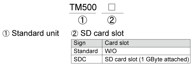
Structure of product code

Download
|
Product catalogue(PDF)
|
⇒Download Page | |
|---|---|---|
|
Operation manual(PDF)
|
||
|
External dimension
|
DXF
(ZIP) |
|
|
PDF
|
||
|
Support tools
|
||
|
Software
|
||


